EN
USER AND SAFETY GUIDE
2-circuit Z-Wav
measurement
READ BEFORE USE
This document contains important technical and safety informa-
tion about the Device, its safe use and installation.
⚠CAUTION! Before beginning the installation, please r
and entirely this guide and any other documents accompanying the
Device. Failure to follow the installation pr
malfunction, danger to your health and life, violation of law or refus-
al of legal and/or commercial guarantee (if any). Allterco Robotics
EOOD is not responsible for any loss or damage in case of incorrect
installation or improper operation of this Device due to failur-
lowing the user and safety instructions in this guide.
TERMINOLOGY
Gateway – A Z-Wa
controller
Z-Wave™ hub, etc., is a device that serves as a centr
Z-Wave™ smart home network. The term “gateway ” is used in this
document.
S button - The Z-W
Z-Wave™ devices and is used for various functions such as adding
(inclusion), removing (exclusion), and resetting the de-
tory default settings. The term "S button " is used in this document.
Device – In this document, the term “Device” is used to ref
Wave 2PM device.
ABOUT SHELL
Shelly Qubino is a line of innovative microprocessor-managed
devices, which allow remote control of electric circuits with a
smartphone, tablet, PC, or home automation system. They work on
Z-Wave™ wireless communication prot
the gateway is connected to the internet, you can control Shelly
Qubino devices remotely from anywhere. Shelly Qubino devices can
be
devices from other manufacturers. All mains operated
the network will act as repeaters regardless of vendor to incr
reliability of the network. Devices are designed to work with older
generations of Z-Wav
ABOUT
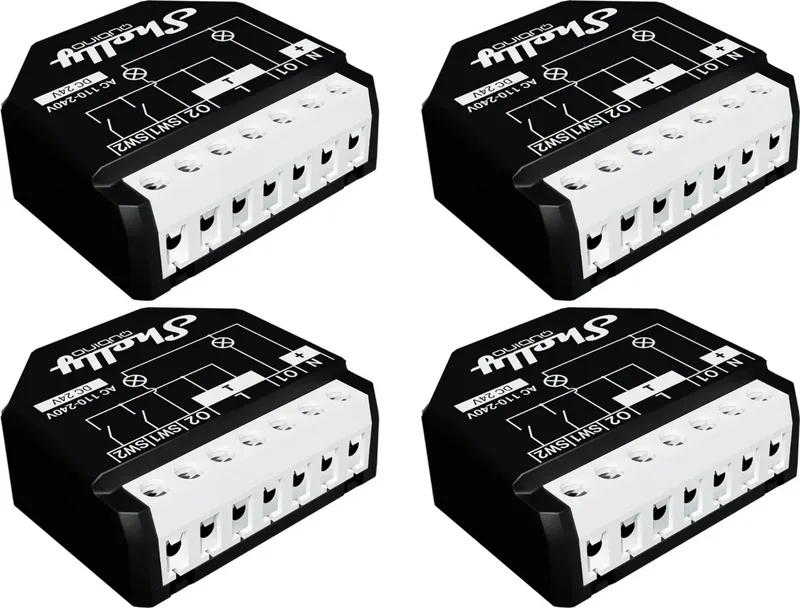
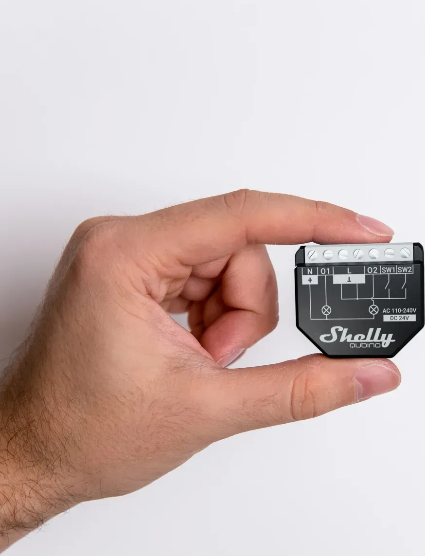
The Wave 2PM (Device) is a single pr
control of two electrical devices such as bulbs, ceiling fans, and
IR heaters. It switches (on/off) two independent loads and mea-
sures their power consumption separately and in total.
is compatible with switches (default) and push-buttons.
ELECTRICAL DIAGRAM (110-240 V AC / 24 V DC
Refer to
INST
The Device can control various types of loads (e.g., bulbs). Each
circuit can support a load up to 10 A (with a total of 16 A for both
circuits) and its power consumption is measured individually and
in total (AC only).
It can be r-
er sockets and light switches or other places with limited space.
⚠CAUTION! Danger of electrocution. Mounting/installation of the
Device to the power grid has to be performed with caution, by a
qualied electrician.
⚠CAUTION! Danger of electrocution. Every change in the connec-
tions has to be done after ensuring there is no voltage present at
the Device terminals.
⚠CAUTION! Use the Device only with a power grid and applianc-
es that comply with all applicable regulations. A short circuit in the
power grid or any appliance connected to the Device may damage it.
⚠CAUTION! Do not connect the Device to appliances exceeding
the given max. load!
⚠CAUTION! Do not shorten the antenna.
⚠RECOMMENDAPlace the antenna as far away as possible
from metal elements as they can cause signal interference.
⚠CAUTION! Connect the Device only in the way shown in these
instructions. Any other method could cause damage and/or injury.
⚠CAUTION! Do not install the Device where it can get wet.
⚠CAUTION! Do not use the Device if it has been damaged!
⚠CAUTION! Do not attempt to service or repair the De
⚠RECOMMENDAConnect the Device using solid single-core
wires with increased insulation heat resistance not less than PVC
T105°C (221°F).
⚠CAUTION! Before starting the mounting/installation of the De-
vice, check that the breakers are turned off and there is no v
on their terminals. This can be done with a phase tester or multime-
ter
connecting the wires.
If you want to use the Device with a push-button, r
and Fig. 4. For a switch, refer to the Fig. 1 and Fig. 3.
⚠CAUTION! Use only one phase AC circuit. Do not use mixed AC
and DC circuits.
For AC circuits connect both L terminals to the Live wir
N terminal to the Neutral wire. Connect the rst load circuits to the
O1 terminal and the Neutral wire. Connect the second load circuits
to the O2 terminal and the Neutral wire.
push-button to the SW1 terminal and the Live wire. Connect the
second switch/push-button to the SW2 terminal and the Live wire.
For DC circuits connect both terminals to the GND wire and the
+ terminal to the Positive wire. Connect
O1 terminal and the Positive wire. Connect the second load circuits
to the O2 terminal and the Positive wire.
push-button to the SW1 terminal and the GND wire. Connect the
second switch/push-button to the SW2 terminal and the GND wire.
⚠RECOMMENDA For inductive appliances that cause volta-
ge spikes during switching on/off, such as electrical motors, fans,
vacuum and RC µF / /
1/2 W / 600 V AC) should be connected parallel t
⚠CAUTION! Do not allow children to play with the push-buttons/
switches connected to the Device. Keep the devices for r
control of Shelly Qubino (mobile phones, tablets, PCs) away from
children.
Z-WA
SmartStar
SmartStart enabled products can be added into a Z-Wave™ network
by scanning the Z-Wave™ QR Code present on the De
gateway providing SmartStart inclusion. No further action is re-
quired, and the SmartStart device will be added automatically with-
in 10 minutes of being switched on in the network vicinity
1. With the gateway application scan the QR code on the Device
label
provisioning list in the gateway
2. Connect the Device to a power supply
3. Check if the blue LED is blinking in Mode 1. If so, the Device is not
added to a Z-Wave™ network.
4. Adding will be initiated automatically within a few seconds after
connecting the Device to a power supply
added to a Z-Wave™ network aut
5. The blue LED will be blinking in Mode 2 during the adding pro-
cess.
6. The loads connected to O1 and O2 will be blinking 1s on/1s
off/1s on/1s off if the Device is successfully added to a Z-Wav
network.
7. The green LED will be blinking in Mode 1 if the Device is success-
fully added to a Z-Wave™ network.
Adding (inclusion) with a switch/push-button:
1. Connect the Device to a power supply
2. Check if the blue LED is blinking in Mode 1. If so, the Device is not
added to a Z-Wave™ network.
3. Enable add/remove mode on the gateway
4. T
terminal 3 times within 3 seconds (this procedure puts the Device
in LEARN MODE*). The Device must receive on/off signal 3 times,
which means pressing the push-button 3 times, or toggling the
switch on and off 3 times.
5. The blue LED will be blinking in Mode 2 during the adding pro-
cess.
6. The loads connected to O1 and O2 will be blinking 1s on/1s
off/1s on/1s off if the Device is successfully added to a Z-Wav
network.
7. The green LED will be blinking in Mode 1 if the Device is success-
fully added to a Z-Wave™ network.
*LEARN MODE state allows the Device to receive network informa-
tion from the gateway
Adding (inclusion) with the S button:
1. Connect the Device to a power supply
2. Check if the blue LED is blinking in Mode 1. If so, the Device is not
added to a Z-Wave™ network.
3. Enable add/remove mode on the gateway
4. T
the Device until the LED turns solid blue.
5. Quickly release and then press and hold (> 2s) the S button on the
Device until the blue LED starts blinking in Mode 3. Releasing the S
button will start the LEARN MODE.
6. The blue LED will be blinking in Mode 2 during the adding pro-
cess.
7. The loads connected to O1 and O2 will be blinking 1s on/1s
off/1s on/1s off if the Device is successfully added to a Z-Wav
network.
8. The green LED will be blinking in Mode 1 if the Device is success-
fully added to a Z-Wave™ network.
Note! In Setting mode, the Device has a timeout of 10s before enter-
ing again into Normal mode.
Note! In case of Security 2 (S2) adding (inclusion), a dialog will ap-
pear asking you to enter the corresponding PIN Code (5 underlined
digits) that are written on the DSK label on the side of the Device
and on the DSK label inserted in the packaging.
Mounting Wall console
Screw terminals max. torque 0.4 Nm / 3.5 lbin
Conductor cross section 0.5 to 1.5 mm² / 20 to 16 A
Conductor stripped length 5 to 6 mm / 0.20 to 0.24 in
Shell material Plastic
Color Black
Ambient temperature -20°C to 40°C / -5°F to 105°F
Humidity 30% to 70% RH
Max. altitude 2000 m / 6562 ft.
IMPORT
Z-Wave™ wireless communication may not alwa
This Device should not be used in situations in which life and/or va-
luables are solely dependent on its functioning. If the Device is not
recognized by your gateway or appears incorr
change the Device type manually and ensure that your gateway sup-
ports Z-Wave Plus™ multi-level devices.
ORDERING CODE: QNSW-002P16XX
XX – Values
DECLARA
Hereby-
ment type Wave 2PM is in compliance with Directiv
2014/35/EU, 2014/30/EU, 2011/65/EU. The full text of the EU de-
claration of conformity is available at the following internet address:
https:/
MANUF
Allterco Robotics EOOD
Address: 103 Cherni vr
Tel.: +359
E-mail: zwave-shelly@shelly
Support: https:/
Web: https:/
Changes in the contact data are published by the Manufacturer at the
ocial website: https:/
DE
BENUTZER- UND SICHERHEITSHANDBUCH
Smarter Z-Wave™-Switch mit 2-Kanal und
Leistungsmessungs
BITTE VOR GEBRAUCH DURCHLESEN
Dieses Dokument enthält wichtige technische und sicherheits-
technische Informationen über das Gerät und seine sichere Ver-
wendung und Installation.
⚠ACHTUNG! Bevor Sie mit der Installation beginnen, lesen Sie
bitte die Begleitdokumentation sorgfältig und vollständig durch.
Die Nichtbeachtung der empfohlenen Verfahren kann zu Fehlfunk-
tionen, Lebensgefahr oder Gesetzesverstößen führen. Allterco Ro-
botics EOOD haftet nicht für Verluste oder Schäden im Falle einer
falschen Installation oder Bedienung dieses Geräts.
TERMINOLOGIE
Gateway - Ein Z-Wave™-Gateway
Z-Wave™-Hauptcontroller
Hub usw
Z-Wave™-Smart-Home-Netzwerk dient. In diesem Dokument wird
der Begriff "Gateway " verwendet.
S-T - Die Z-Wave™ Service-T
bendet und für verschiedene Funktionen wie die Aufnahme
(Hinzufügen), der Ausschluss (Entfernen) und das Zurücksetzen
des Geräts auf die Werkseinstellungen verwendet wird. In diesem
Dokument wird der Begriff "S-T" verwendet.
Gerät - In diesem Dokument wird der Begriff "Gerät" für das W
2PM Gerät verwendet.
ÜBER SHELL
Shelly Qubino ist eine Reihe innovativer-
er Geräte, die die Fernsteuerung von Stromkr
Smartphone, T
ermöglichen. Sie arbeiten mit dem drahtlosen Z-Wav-
nikationsprotokoll unter Verwendung eines Gateways. W
Gateway mit dem Internet verbunden ist, können Sie die Shelly
Qubino Geräte von überall
können jedem -
zierten Geräten anderer Hersteller betrieben werden. Alle netzbe-
triebenen Knotenpunkte innerhalb des Netzwerks werden unabhän-
gig vom Hersteller als Repeater fungieren, um die Zuverlässigkeit
des Netzwerks zu erhöhen. Die Geräte sind so konzipiert, dass
sie mit älteren Generationen von Z-W
funktionieren.
ÜBER DAS WA
Das Wave 2PM (Ger-
steuerung von zwei elektrischen Geräten wie Glühbirnen, Decken-
ventilatoren und IR-Heizungen ermöglicht. Es schaltet (ein/aus)
zwei unabhängige Lasten und misst deren Stromverbr
und insgesamt. Das Gerät ist mit Schaltern (Standard) und Druck-
knöpfen kompatibel.
ELEKTRISCHER SCHAL
(110–240V AC / 24 V DC)
Sehen Sie sich die Schaltpläne (Abb. 1–4) in diesem Benutzerhandbuch an.
INST
Das Gerät kann verschiedene Arten von Lasten (z. B. Glühbirnen)
steuern. Jeder Stromkreis kann mit bis zu 10 A belastet werden
(insgesamt 16 A für beide Stromkreise), und der Stromverbr
wird einzeln und in Summe gemessen (nur AC).
Es kann in eine Standard-Unterputzkonsole nachgerüstet werden,
hinter Steckdosen und Lichtschaltern oder an anderen Orten mit
begrenztem Platz vorgesehen.
⚠VORSICHT! Gefahr eines Stromschlages. Die Montage/Installa-
tion des Geräts an das Stromnetz muss von einem qualifizierten
Elektriker mit Vorsicht durchgeführt werden!
⚠VORSICHT! Es besteht Stromschlaggefahr
der Anschlüsse muss sichergestellt werden, dass an den Klemmen
des Geräts keine Spannung anliegt!
⚠VORSICHT! Verwenden Sie das Gerät nur mit einem Stromnetz
und Geräten, die allen geltenden Vorschriften entspr
Kurzschluss im Stromnetz oder in einem an das Gerät angeschlos-
senen Gerätes kann dieses beschädigen!
⚠VORSICHT! Schließen Sie das Gerät nicht an Geräte an, die die
angegebene Höchstlast überschreiten!
⚠VORSICHT! Kürzen Sie die Antenne nicht!
⚠EMPFEHLUNG: Stellen Sie die Antenne möglichst weit von
metallischen Gegenständen auf, da diese Signalstörungen verur-
sachen können.
⚠VORSICHT! Schließen Sie das Gerät nur auf die in dieser Anlei-
tung beschriebene Weise an. Jede andere Methode kann zu Schä-
den und/oder Verletzungen führen!
⚠VORSICHT! Installieren Sie das Gerät nicht an einem Ort, an dem
es nass werden kann!
⚠VORSICHT! Verwenden Sie das Gerät nicht, wenn es beschädigt ist!
⚠VORSICHT! Versuchen Sie nicht, das Gerät selbst zu
oder zu reparieren!
⚠EMPFEHLUNG: Schließen Sie das Gerät mit massiven einadri-
gen Kabeln mit erhöhter Isolationswärmebeständigkeit von min-
destens PVC T105°C (221°F) an!
⚠VORSICHT! Bevor Sie mit der Installation/Montage des Geräts
beginnen, prüfen Sie, ob die Leitungsschutzschalter (Sicherungen)
ausgeschaltet sind und keine Spannung an den Klemmen anliegt.
Dies kann mit einem Phasenprüfer oder Multimeter erfolgen. Wenn
Sie sicher sind, dass keine Spannung anliegt, können Sie mit dem
Anschluss der Kabel for
Wenn Sie das Gerät mit einem Druckknopf verwenden wollen, se-
hen Sie sich Abb. 2 und Abb. 4 an. Für einen Schalter
1 und Abb. 3.
⚠VORSICHT! Verwenden Sie nur einen einphasigen W-
stromkreis. Verwenden Sie keine gemischten A-
kreise.
Bei Wechselstromkreisen schließen Sie beide Klemmen L an das
stromführende Kabel und die Klemme N an das neutrale Kabel an.
Schließen Sie den ersten Laststromkreis an die Klemme O1 und das
Nullleiterkabel an. Schließen Sie den zweiten Laststromkreis an die
Klemme O2 und das Nullleiterkabel an. Schließen Sie den ersten
Schalter/Druckknopf an die Klemme SW1 und das stromführende
Kabel an. Schließen Sie den zweiten Schalter an die Klemme SW2
und das stromführende Kabel an.
Bei Gleichstromkreisen schließen Sie beide Klemmen an das
Massekabel und die Klemme + an das Pluskabel an. Schließen
Sie die ersten Lastkreise an die Klemme O1 und das Pluskabel an.
Schließen Sie die zweiten Lastkreise an die Klemme O2 und das
Pluskabel an. Schließen Sie den ersten Schalter/Druckknopf an die
Klemme SW1 und das Massekabel an. Schließen Sie den zweiten
Schalter/Druckknopf an die Klemme SW2 und das Massekabel an.
⚠EMPFEHLUNG: Bei induktiven Ger-
schalten Spannungsspitzen verursachen, wie z. B. Elektromotoren,
Ventilatoren, Staubsauger und ähnliche, sollte ein RC-Snubber (0,1 µF /
100 Ω /
⚠VORSICHT! Erlauben Sie Kindern nicht, mit den an das Gerät an-
geschlossenen T
zur Fernsteuerung des Shelly Qubino (z.B.: Mobiltelefone, T
PCs) von Kindern fern.
Z-WA
AUSSCHLUSS)
Hinzufügen (Aufnahme) von SmartStart:
SmartStart-fähige Produkte können in ein Z-Wave™-Netzwerk
aufgenommen werden, indem der Z-Wav
Gerät mit einem Gateway gescannt wird, das die SmartStart-Ein-
bindung ermöglicht. Es sind keine weiteren Schritte erforderlich,
und das SmartStart-Gerät wird innerhalb von 10 Minuten nach dem
Einschalten automatisch in der Nähe des Netzwerks hinzugefügt.
Modus "Einstellung im Gange"
Zurücksetzen auf die Werkseinstellun-
gen und Neustart
Blau/
Rot/
Grün
**
Hinzufügen/Entfernen (Aufnahme/
Ausschluss)
Blau Modus 2
Überprüfung der Stromv
AC Frequenz
Blau/
Rot
Modus 5
Firmware-Aktualisierung OT Blau/
Rot
Modus 2
Alarmmodus
Überstrom erkannt O (O1 + O2) Rot Modus 4 (1x)
Überhitzung erkannt Rot Modus 4 (2x)
Fehler in der Stromversorgung (Fehler
in
Spannung)
Rot Modus 4 (3x)
Überstrom erkannt O1 Rot Modus 4 (4x)
Überstrom erkannt O2 Rot Modus 4 (5x)
** Die
blaue und rote LED im Modus 3 für ca. 2s zu blinken.
Die LED schaltet sich 30 Minuten nach dem Stromzyklus aus. Jedes
Mal, wenn Sie die S-T
Wenn der Alarm aktiv ist, schaltet sich die LED nicht aus.
BETRIEBLICHE ANWEISUNGEN
Wenn und kongurier (Standardeinstel-
lung), werden die Ausgänge O1 und O2 bei jedem Umschalten des
Schalters in den entgegengesetzten Zustand versetzt - ein, aus, ein,
usw
Wenn -
riert sind, ändert jeder Druck die Zustände der Ausgänge O1 und O2 in
entgegengesetzte Zustände - ein, aus, ein, usw
UNTERSTÜTZTE LASTTYPEN
• Widerstandsfähig (Glühbirnen, Heizgeräte)
• Kapazitiv (Kondensatorbatterien, elektronische Ger-
startkondensatoren)
• Induktiv mit RC Snubber (LED-Lichttreiber-
tilatoren, Kühlschr
SPEZIFIKA
Energieversorgung 110-240 V CA / 24 V CC +/- 10%
Stromverbrauch < 0.3 W
Leistungsmessung (W) Ja
Max. Schaltspannung
Wechselstrom AC
240 V
Max. Schaltstrom
Wechselstrom AC
10 A pro Kanal, 16 A insgesa-
mt, 18 A im Peak
Max. Schaltspannung
Gleichstrom DC
30 V
Max. Schaltstrom Gleichstrom
DC
10 A
Überhitzungsschutz Ja
Überstromschutz Ja
Entfernung Bis zu 40 m in Innenräumen
(131 ft.) (abhängig von den
örtlichen Gegebenheiten)
Z-Wave™ Repeater Ja
CPU Z-Wave™ S800
Z-Wave™ Fr 868,4 MHz; 865,2 MHz; 869,0
MHz; 921,4 MHz; 908,4 MHz;
916 MHz; 919,8 MHz; 922,5
MHz; 919,7-921,7-923,7 MHz;
868,1 MHz; 920,9 MHz
Maximale übertragene
Funkfrequenzleistung in
Frequenzband(en)
< 25 mW
Größe (H × B × T) 37x42x16 ±0.5 mm /
1.46x1.65x0.63 ±0.02 in
Gewicht 29 g / 1.02 oz.
Montage Wandkonsole
Schraubklemmen max.
Drehmoment
0.4 Nm / 3.5 lbin
Querschnitt des Leiters 0.5 bis 1.5 mm² / 20 bis 16
AWG
Länge des abisolierten Leiters 5 bis 6 mm / 0.20 bis 0.24 in
Gehäusematerial Kunststoff
Farbe Schwarz
Umgebungstemperatur -20°C bis 40°C / -5°F bis 105°F
Luftfeuchtigkeit 30% bis 70% RH
Max. Höhe 2000 m / 6562 ft.
WICHTIG
Die Z-Wave™ drahtlose K-
lässlich. Dieses Modul soll nicht in Situationen verwendet werden,
in denen menschliches Leben oder Wertgegenstände allein von der
Funktion des Moduls abhängen. Falls das Modul von Ihrem Contr
nicht erkannt oder falsch angezeigt wird, müssen Sie eventuell den
Gerätetyp manuell eingeben und sicherstellen, dass ihr Gateway- Con-
troller Z-Wave Plus™ Helligkeitsr
BESTELLCODES : QNSW
XX - Werte geben die Produktversion bezogen auf die Region an.
KONFORMIT
Hiermit erklärt Allterco Robotics EOOD, dass der F
Wave 2PM der Richtlinie 2014/53/EU, 2014/35/EU, 2014/30/EU,
2011/65/EU entspricht. Den vollständigen T-
erklärung nden Sie unter folgender Internetadresse:
https:/
HERSTELLER:
Allterco Robotics EOOD
Adresse: 103 Cherni vr
Tel.: +359
E-mail: zwave-shelly@shelly
Kundensupport: https:/
Ozielle Website: https:/
Änderungen der Kontaktdaten werden vom Hersteller auf dessen o-
ziellen Website veröffentlicht: https:/
IT
GUIDA ALL
Interruttore intelligente Z-W
con misurazione della potenza
LEGGERE PRIMA DELL
Questo documento contiene importanti informazioni tecniche e di
sicurezza sul Dispositivo e sul suo uso e installazione in sicurezza.
⚠A Prima di iniziare l’installazione leggere attenta-
mente e completamente la documentazione allegata. La mancata
osservanza delle procedure consigliate potrebbe portare a malfun-
zionamenti, pericolo per la vita o violazione della legge. Allterco
Robotics EOOD non è responsabile per eventuali perdite o danni in
caso di installazione o funzionamento errati di questo Dispositiv
TERMINOLOGIA
Gateway – Un gateway Z-Wave™, anche chiamat
Z-Wave™, controller principale Z-W
dispositivo che funge da hub centrale per una rete domestica in-
telligente in tecnologia Z-Wave™. In questo document
semplicemente il termine "gateway ".
Pulsante S – E’ il pulsante di Servizio Z-Wave™, che si trov
dispositivi Z-Wave™ e viene utilizzato per v
l'inclusione (aggiunta), l'esclusione (rimozione) e il ripristino delle
impostazioni predenite -
mento si utilizzerà semplicemente il termine "pulsante S ".
Dispositivo - In questo documento, il termine "Dispositivo
utilizzato per fare riferimento al dispositiv
A PROPOSITO DI SHELL
Shelly Qubino è una linea di dispositivi innovativi gestiti da micro-
processore, che consentono il controllo remot
con smartphone, tablet, PC o sistema domotico. Funzionano su
protocollo di comunicazione wireless Z-Wa
gateway
i dispositivi Shelly Qubino in remoto da qualsiasi luogo. I dispositivi
Shelly Qubino possono essere utilizzati in qualsiasi rete Z-Wa
con altri dispositivi
gestiti dalla rete all'interno della rete fungeranno da ripetit-
endentemente dal
dispositivi sono progettati per funzionare con le generazioni pr-
edenti di dispositivi e gateway Z-Wave™.
A PROPOSITO DI W
Il Dispositivo Wave 2PM è un singolo prodott-
trollo remoto di due dispositivi elettrici come lampadine, ventilatori
a
due carichi indipendenti e ne misura il consumo energetico in modo
separato e totale. Il Dispositiv-
IMPORT
Removing (exclusion) with a switch/push-button:
1. Connect the Device to a power supply
2. Check if the green LED is blinking in Mode 1. If so, the Device is
added to a Z-Wave™ network.
3. Enable add/remove mode on the gateway
4. T
terminal 3 times within 3 seconds (this procedure puts the Device
in LEARN MODE*). The Device must receive on/off signal 3 times,
which means pressing the push-button 3 times, or toggling the
switch on and off 3 times.
5. The blue LED will be blinking in Mode 2 during the removing
process.
6. The loads connected to O1 and O2 will be blinking 1s on/1s
off/1s on/1s off if the Device is successfully removed from a
Z-Wave™ network.
7. The blue LED will be blinking in Mode 1 if the Device is success-
fully removed from a Z-Wa
Removing (exclusion) with the S button:
1. Connect the Device to a power supply
2. Check if the green LED is blinking in Mode 1. If so, the Device is
added to a Z-Wave™ network.
3. Enable add/remove mode on the gateway
4. T
the Device until the LED turns solid blue.
5. Quickly release and then press and hold (> 2s) the S button on the
Device until the blue LED starts blinking in Mode 3. Releasing the
S button will start the LEARN MODE.
6. The blue LED will be blinking in Mode 2 during the removing
process.
7. The loads connected to O1 and O2 will be blinking 1s on/1s
off/1s on/1s off if the Device is successfully removed from a
Z-Wave™ network.
8. The blue LED will be blinking in Mode 1 if the Device is success-
fully removed from a Z-Wa
Note! In Setting mode, the Device has a timeout of 10s before enter-
ing again into Normal mode.
F
After Factory reset, all custom par
associations, routings, etc.) will return to their default state. HOME
ID and NODE ID assigned to the Device will be deleted. Use this
reset procedure only when the gateway is missing or otherwise
inoperable.
Factory reset with a switch/push-butt
Note! Factory reset with the switch/push-button is only possible with-
in the rst minute after
1. Connect the Device to a power supply
2. T
terminal 5 times within 3 seconds. The Device must receive on/off
signal 5 times, which means pressing the push-button 5 times, or
toggling the switch on and off 5 times.
3. During factory reset, the LED will turn solid green for about 1s,
then the blue and red LED will start blinking in Mode 3 for approx. 2s.
4. The blue LED will be blinking in Mode 1 if the Fact
successful.
Factory reset with the S butt
Note! Factory reset with the S button is possible anytime.
1. T
the Device until the LED turns Solid blue.
2. Press the S button multiple times until the LED turns Solid red.
3. Press and hold (> 2s) S button on the Device until the r
starts blinking in Mode 3. Releasing the S button will start the fac-
tory reset.
4. During factory reset, the LED will turn solid green for about 1s,
then the blue and red LED will start blinking in Mode 3 for approx.
2s.
5. The blue LED will be blinking in Mode 1 if the Fact
successful.
NOTE: For more information about this Device r
User Guide available at: https:/
LED SIGNALIZA
LED blinking modes
Mode 1 0,5s On/2s Off
Mode 2 0,5s On/0,5s Off
Mode 3 0,1s On/0,1s Off
Mode 4 (1x to 6x - 0,2s On/0,2s Off) +
2s Off
Mode 5 0,2s On blue/0,2s On red
Normal mode Colour LED mode
Removed/Excluded Blue Mode 1
Added/Included Green Mode 1
Setting mode (with S button)
Adding/Removing (Inclusion/Exclusion)
menu selected
Blue Solid
Adding/Removing (Inclusion/Exclusion)
menu - while pressing S button -
Adding/Removing (Inclusion/Exclusion)
process selected
Blue Mode 3
Factory reset menu selected Red Solid
Factory reset - while pressing S button -
Factory reset process selected
Red Mode 3
“Setting in progress” mode
Factory reset and reboot Blue/
Red/
Green
**
Adding/Removing (Inclusion/Exclusion) Blue Mode 2
Checking power supply 230 V AC
frequency or 24 V DC voltage
Blue/
Red
Mode 5
OT Blue/
Red
Mode 2
Alarm mode
Overcurrent detected O (O1 + O2) Red Mode 4 (1x)
Overheat detected Red Mode 4 (2x)
Power supply fault (power supply 230 V
AC frequency or 24 V DC voltage fault)
Red Mode 4 (3x)
Overcurrent detected O1 Red Mode 4 (4x)
Overcurrent detected O2 Red Mode 4 (5x)
** LED will turn solid green for about 1s, then the blue and red LED
will start blinking in Mode 3 for approx. 2s.
LED will turn off 30 minutes after the power cycle. Every time you press
on the S button, the LED will turn on for 30 minutes. If alarm is active,
LED will not turn off.
OPERA
If the each tog-
gle of the switch will change the outputs O1 and O2 states to the
opposite states - on, off, on, etc.
If the
settings, each press of the push-button will change the outputs O1
and O2 states to opposite states - on, off, on, etc.
SUPPORTED LOAD TYPES
• Resistive (incandescent bulbs, heating devices)
• Capacitive (capacitor banks, electronic equipment, motor start
capacitors)
• Inductive with RC Snubber (LED light drivers, transformers, fans,
refrigerators, air-conditioners)
SPECIFICA
Power supply 110-240 V AC / 24 V DC +/- 10%
Power consumption < 0.3 W
Power measurement (W) Yes
Max. switching voltage AC 240 V
Max. switching current AC 10 A per channel, 16 A total, 18
A total peak
Max. switching voltage DC 30 V
Max. switching current DC 10 A
Overheating protection Yes
Overcurrent protection Yes
Distance Up to 40 m indoors (131 ft.)
(depends on local condition)
Z-Wave™ repeater Yes
CPU Z-Wave™ S800
Z-Wave™ frequency bands 868,4 MHz; 865,2 MHz; 869,0
MHz; 921,4 MHz; 908,4 MHz;
916 MHz; 919,8 MHz; 922,5
MHz; 919,7-921,7-923,7 MHz;
868,1 MHz; 920,9 MHz
Maximum radio frequency
power transmitted in frequency
band(s)
< 25 mW
Size (H x W x D) 37x42x16 ±0.5 mm /
1.46x1.65x0.63 ±0.02 in
Weight 29 g / 1.02 oz..
1. Scannen Sie mit der Gateway-Anwendung den QR-Code auf dem
Geräteetikett und fügen Sie den Security 2 (S2) Device Specic K
(DSK) zur Provisioning List im Gateway hinzu.
2. Schließen Sie das Gerät an eine Stromversorgung an.
3. Prüfen Sie, ob die blaue LED in Modus 1 blinkt. Ist dies der Fall,
wird das Gerät nicht in ein Z-Wa
4. Die Aufnahme (Hinzufügen) wird automatisch innerhalb weniger
Sekunden nach dem Anschluss des Geräts an die Stromversorgung
eingeleitet und das Gerät wird automatisch in das Z-W-
erk aufgenommen.
5. Die blaue LED blinkt im Modus 2 während des Aufnahmevor-
gangs (Hinzufügen).
6. Die an O1 und O2 angeschlossenen Lasten blinken 1 s
Ein/1 s Aus/1 s Ein/1 s A wenn das Gerät erfolgreich in ein
Z-Wave™-Netzwerk hinzugefügt wurde.
7. Die grüne LED blinkt im Modus 1, wenn das Gerät erfolgreich zu
einem Z-Wave™-Netzwerk hinzugefügt wurde.
Hinzufügen (Aufnahme) mit einem Schalter/Druckknopf:
1. Schließen Sie das Gerät an eine Stromversorgung an.
2. Prüfen Sie, ob die blaue LED in Modus 1 blinkt. Ist dies der Fall,
wird das Gerät nicht in ein Z-Wa
3. Aktivieren Sie den Hinzufügen/Entfernen-Modus auf dem Gateway
4. Schalten Sie den Schalter/Druckknopf, der an die Klemme SW1
oder SW2 verbunden ist, 3 Mal innerhalb von 3 Sekunden um (dies-
er Vorgang versetzt das Ger
muss 3 Mal ein Ein/Aus-Signal empfangen, d. h. 3 Mal den Druck-
knopf drücken oder den Schalter 3 Mal ein- und ausschalten.
5. Die blaue LED blinkt im Modus 2 während des Aufnahmevor-
gangs (Hinzufügen).
6. Die an O1 und O2 angeschlossenen Lasten blinken 1 s
Ein/1 s Aus/1 s Ein/1 s A wenn das Gerät erfolgreich in ein
Z-Wave™-Netzwerk hinzugefügt wurde.
7. Die grüne LED blinkt im Modus 1, wenn das Gerät erfolgreich zu
einem Z-Wave™-Netzwerk hinzugefügt wurde.
*Der Status LEARN MODE ermöglicht es dem Gerät, Netzwerkinfor-
mationen vom Gateway zu empfangen.
Hinzufügen (Aufnahme) mit der S-T
1. Schließen Sie das Gerät an eine Stromversorgung an.
2. Prüfen Sie, ob die blaue LED in Modus 1 blinkt. Ist dies der Fall,
wird das Gerät nicht in ein Z-Wa
3. Aktivieren Sie den Hinzufügen/Entfernen-Modus auf dem Gate-
w
4. Um den Einstellungsmodus aufzurufen, halten Sie die S-T
auf dem Gerät kurz gedrückt, bis die LED dauerhaft blau leuchtet.
5. Lassen Sie die S-T
dann gedrückt (> 2 bis die blaue im Modus zu blinken
beginnt. Wenn Sie die S-T
gestartet.
6. Die blaue LED blinkt im Modus 2 während des Aufnahmevor-
gangs (Hinzufügen).
7. Die an O1 und O2 angeschlossenen Lasten blinken 1 s
Ein/1 s Aus/1 s Ein/1 s A wenn das Gerät erfolgreich in ein
Z-Wave™-Netzwerk hinzugefügt wurde.
8. Die grüne LED blinkt im Modus 1, wenn das Gerät erfolgreich zu
einem Z-Wave™-Netzwerk hinzugefügt wurde.
Achtung! Im Einstellungsmodus hat das Gerät einen Timeout v
10s, bevor es wieder in den Normalmodus wechselt.
Achtung! Im Falle der Aufnahme (Hinzufügen) von Security 2 (S2)
erscheint ein Dialog, in dem Sie aufgefordert werden, die entsprech-
ende PIN-Code (5 unterstrichene Ziffern) einzugeben, die auf dem
DSK-Etikett an der Seite des Ger
Verpackung angegeben ist.
WICHTIG: Der PIN-Code darf nicht verloren gehen.
Entfernen (Ausschluss) mit dem Schalter/Druckknopf:
1. Schließen Sie das Gerät an eine Stromversorgung an.
2. Prüfen Sie, ob die grüne LED in Modus 1 blinkt. Wenn ja, wird das
Gerät zu einem Z-Wav
3. Aktivieren Sie den Hinzufügen/Entfernen-Modus auf dem Gate-
w
4. Schalten Sie den Schalter/Druckknopf, der an die Klemme SW1
oder SW2 verbunden ist, 3 Mal innerhalb von 3 Sekunden um (dies-
er Vorgang versetzt das Ger
muss 3 Mal ein Ein/Aus-Signal empfangen, d. h. 3 Mal den Druck-
knopf drücken oder den Schalter 3 Mal ein- und ausschalten.
5. Die blaue LED blinkt im Modus 2 während des Ausschlussver-
fahrens (Entfernen).
6.
Aus/1 s Ein/1 s Aus, wenn das Gerät erfolgreich aus einem
Z-Wave™-Netzwerk entfernt wur
7. Die blaue LED blinkt im Modus 1, wenn das Gerät erfolgreich aus
einem Z-Wave™-Netzwerk entfernt wur
Entfernen (Ausschluss) mit der S-T
1. Schließen Sie das Gerät an eine Stromversorgung an.
2. Prüfen Sie, ob die grüne LED in Modus 1 blinkt. Wenn ja, wird das
Gerät zu einem Z-Wav
3. Aktivieren Sie den Hinzufügen/Entfernen-Modus auf dem Gate-
w
4. Um den Einstellungsmodus aufzurufen, halten Sie die S-T
auf dem Gerät kurz gedrückt, bis die LED dauerhaft blau leuchtet.
5. Lassen Sie die S-T
dann gedrückt (> 2 s), bis die blaue LED im Modus 3 zu blinken
beginnt. Wenn Sie die S-T
gestartet.
6. Die blaue LED blinkt im Modus 2 während des Ausschlussver-
fahrens (Entfernen).
7.
Aus/1 s Ein/1 s Aus, wenn das Gerät erfolgreich aus einem
Z-Wave™-Netzwerk entfernt wur
8. Die blaue LED blinkt im Modus 1, wenn das Gerät erfolgreich aus
einem Z-Wave™-Netzwerk entfernt wur
Achtung! Im Einstellungsmodus hat das Gerät einen Timeout von
10 s, bevor es wieder in den Normalmodus wechselt.
ZURÜCKSETZEN AUF DIE WERKSEINSTELLUNGEN
Nach dem Zurücksetzen auf die Werkseinstellungen werden alle
benutzerdenierten Par und gespeicherten Werte (kWh,
Zuordnungen, Routings usw-
gesetzt. HOME ID und NODE ID
werden gelöscht. Verwenden Sie dieses Verfahr-
zen nur
funktionsfähig ist.
Zurücksetzen auf die Werkseinstellungen mit dem
Schalter/Druckknopf:
Achtung! Das Zurücksetzen auf die Werkseinstellungen mit dem
Schalter/Druckknopf ist nur innerhalb der ersten Minute möglich,
nachdem das Gerät an eine Stromversorgung angeschlossen
wurde.
1. Schließen Sie das Gerät an eine Stromversorgung an.
2. Schalten Sie den Schalter/Druckknopf, der mit der Klemme SW1
oder SW2 verbunden ist, 5 Mal innerhalb von 3 Sekunden um. Das
Gerät muss 5 Mal ein Ein/Aus-Signal empfangen, d. h. 5 Mal den
T
3. Während des Zurücksetzens auf die W
die LED für ca. 1s durchgehend grün, dann beginnen die blaue und
rote LED im Modus 3 für ca. 2s zu blinken.
4. Die blaue LED blinkt im Modus 1, wenn das Zurücksetzen auf die
Werkseinstellungen erfolgreich war
Zurücksetzen auf die Werkseinstellungen mit der
S-T
Achtung! Das Zurücksetzen auf die W
S-T
1. Um den Einstellungsmodus aufzurufen, halten Sie die S-T
auf dem Gerät kurz gedrückt, bis die LED blau leuchtet.
2. Drücken Sie die S-T
3. Halten Sie (>2 s)
im Modus 3 zu blinken beginnt. Wenn Sie die S-T
wird der Werksreset gestartet.
4. Während des Zurücksetzens auf die W
die LED für ca. 1s durchgehend grün, dann beginnen die blaue und
rote LED im Modus 3 für ca. 2s zu blinken.
5. Die blaue LED blinkt im Modus 1, wenn das Zurücksetzen auf die
Werkseinstellungen erfolgreich war
HINWEIS: Weitere Informationen zu diesem Gerät nd-
en Sie im Erweiterten Benutzerhandbuch auf der Website:
https:/
LED-SIGNALISIERUNG
LED-Blinkmodus
Modus 1 0,5 s Ein/2 s Aus
Modus 2 0,5 s Ein/0,5 s Aus
Modus 3 0,1 s Ein/0,1 s Aus
Modus 4 (1x bis 6x - 0,2 s Ein/0,2 s Aus)
+ 2 s Aus
Modus 5 0,2s Auf blau/0,2s Auf rot
Normalmodus Farbe LED-Modus
Entfernt/Ausgeschlossen Blau Modus 1
Hinzugefügt/Aufgenommen Grün Modus 1
Einstellungsmodus (mit der S-T
Menü Hinzufügen/Entfernen (Auf-
nahme/Ausschluss) ausgewählt
Blau Dauerhaft
Menü Hinzufügen/Entfernen (Aufnahme/
Ausschluss) - bei gedrückter S-T
Prozess Hinzufügen/Entfernen (Aufnahme/
Ausschluss) ausgewählt
Blau Modus 3
Menü Zurücksetzen auf die Werksein-
stellungen ausgewählt
Rot Dauerhaft
Zurücksetzen auf die Werkseinstellun-
gen - bei gedrückter S-T-
zen auf die Werkseinstellungen Proz
ausgewählt
Rot Modus 3
denito) e pulsanti.
SCHEMA ELETTRICO (110-240 V CA / 24 V CC)
Fare riferimento agli schemi (Fig. 1-4) in questa guida per l'utente.
ISTRUZIONI PER L
Il Dispositivo può controllare diversi tipi di carichi (ad esempio, lam-
padine). Ogni circuito può supportare un carico
totale di 16 A per entrambi i circuiti) e il consumo ener
misurato individualmente e in totale (solo in corr
Può essere adattato a una console da incasso standard, dietro
prese di corrente e interruttori della luce o in altri luoghi con spazio
limitato.
⚠A Pericolo di folgorazione. Il montaggio/installa-
zione del Dispositivo alla rete elettrica deve essere eseguit
cautela da un elettricista qualificato.
⚠A Pericolo di folgorazione. Ogni modifica dei colle-
gamenti deve essere effettuata dopo essersi assicur
sia tensione sui terminali del Dispositivo.
⚠AUtilizzare il Dispositivo solo con una rete elettrica
e con apparecchi conformi a tutte le norme vigenti. Un cortocircuito
nella rete elettrica o in qualsiasi apparecchio collegato al Disposi-
tivo può danneggiarlo.
⚠A Non collegare il Dispositivo ad apparecchi che
superano il carico massimo indicato!
⚠ANon accorciare l'antenna.
⚠RACCOMANDAZIONE: Posizionare l'
possibile da elementi metallici in quanto essi potrebbero causare
interferenze di segnale.
⚠ACollegare il Dispositivo solo nel modo indicato in
queste istruzioni. Qualsiasi altro metodo potrebbe causare danni
e/o lesioni.
⚠ANon installar
bagnarsi.
⚠ANon utilizzare il Dispositivo se è stato danneggiato!
⚠A Non tentare di riparare o riparare il Dispositivo
da soli!
⚠RACCOMANDAZIONE: Collegare il Dispositivo utilizzando cavi
unipolari solidi con una maggiore resistenza termica dell'isolamen-
to non inferiore a PVC
⚠A Prima di iniziare l'installazione/montaggio del
Dispositivo, controllare che gli interruttori siano spenti e che non
ci sia tensione sui loro terminali. Questo può essere fatto con un
misuratore di fase o un multimetr
tensione, potete procedere al collegamento dei cavi.
Se si desidera utilizzare il Dispositivo con un pulsante, far-
mento alla Fig. 2 e alla Fig. 4. Per un interruttore, far
alla Fig. 1 e alla Fig. 3.
⚠A Utilizzare solo un circuito CA monofase. Non uti-
lizzare circuiti misti CA e CC.
Per i circuiti CA, collegare entrambi i terminali L al ca-
sione e il terminale N al cavo neutro. Collegare i primi circuiti di
carico al terminale O1 e al cavo neutro. Collegare i secondi circuiti
di carico al terminale O2 e al cavo neutro. Collegare il primo interrut-
tore/pulsante al terminale SW1 e al cavo sotto tensione. Collegar
il secondo interruttore al terminale SW2 e al cavo sotto tensione.
Per i circuiti CC, collegare entrambi i terminali al cavo GND e il
terminale + al cavo positivo. Collegare i primi circuiti di carico al
terminale O1 e al cavo positivo. Collegare i secondi circuiti di carico
al terminale O2 e al cavo positivo. Collegare il primo interrutt
pulsante al terminale SW1 e al cavo GND-
terruttore/pulsante al terminale SW2 e al cavo GND
⚠RACCOMANDAZIONE: Per gli apparecchi induttivi che causano
picchi di tensione durante l'accensione e lo spegniment
motori elettrici, ventilatori, aspirapolv-
legare in parallelo all'apparecchio uno
1/2 W / 600 V CA).
⚠ANon permettere ai bambini di giocare con i pul-
santi/interruttori collegati al Dispositivo. T
il controllo remoto di Shelly Qubino (telefoni cellulari, tablet, PC
lontano dai bambini.
AGGIUNT
Aggiunta (inclusione) SmartStar
Se il tuo gateway fornisce l'inclusione SmartStart, i prodotti abilitati
SmartStart possono essere aggiunti a una rete Z-Wave™ scansion-
ando il codice QR Z-Wave™ presente sul Dispositiv
necessarie ulteriori azioni e il dispositivo SmartStart verrà aggiunto
automaticamente entro 10 minuti dall'accensione
della rete.
1. Utilizzando l'applicazione del gateway
sull'etichetta Dispositivo e aggiungere la Device Specic Key
(DSK) Security 2 (S2) all'elenco di pro
2. Collegare il Dispositivo a un alimentazione.
3. Controllare se il LED blu lampeggia in modalità 1. In tal caso, il
Dispositivo non è ancora stato aggiunt
4. L-
chi secondi dal collegamento del Dispositivo a un alimentazione e
il Dispositivo verrà aggiunto aut
5. Il LED blu lampeggerà in modalità 2 durante il pr-
sione (aggiunta).
6. I carichi collegati a O1 e O2 lampeggiano per 1s on/1s off/1s
on/1s off quando il Dispositivo risulterà aggiunto correttamente
una rete Z-Wave™.
7. Il LED verde lampeggerà in modalità 1 se il Dispositiv-
giunto correttamente a una rete Z-Wa
Aggiunta (inclusione) con interruttore/pulsante:
1. Collegare il Dispositivo a un alimentazione.
2. Controllare se il LED blu lampeggia in modalità 1. In tal caso, il
Dispositivo non è ancora stato aggiunt
3. Abilitare la modalità aggiungi/rimuovi sul gateway
4. Azionare 3 volte nell'arco di
collegato al terminale SW1 o SW2 (questa procedura pone il Dis-
positivo in LEARN MODE*). Il Dispositivo deve ricever
di -
sante per 3 volte o accendere e spegnere l'interruttor
5. Il LED blu lampeggerà in modalità 2 durante il pr-
sione (aggiunta).
6. I carichi collegati a O1 e O2 lampeggiano per 1s acceso/1s spen-
to/1s acceso/1s spento quando il Dispositivo risulter
correttamente a una rete Z-Wav
7. Il LED verde lampeggerà in modalità 1 se il Dispositiv-
giunto correttamente a una rete Z-Wa
*Lo stato LEARN MODE consente al Dispositivo di ricevere infor-
mazioni di rete dal gateway
Aggiunta (inclusione) con il pulsante S:
1. Collegare il Dispositivo a un alimentazione.
2. Controllare se il LED blu lampeggia in modalità 1. In tal caso, il
Dispositivo non è ancora stato aggiunt
3. Abilitare la modalità aggiungi/rimuovi sul gateway
4. Per accedere alla modalità di impostazione, premere r-
mente
non diventa blu sso.
5. Rilasciare rapidamente e quindi tenere pr
S Dispositivo il LED lampeggiare
modalità 3. Rilasciando il pulsante S si avvia la LEARN MODE.
6. Il LED blu lampeggerà in modalità 2 durante il pr-
sione (aggiunta).
7. I carichi collegati a O1 e O2 lampeggiano per 1s acceso/1s spen-
to/1s acceso/1s spento quando il Dispositivo risulter
correttamente a una rete Z-Wav
8. Il LED verde lampeggerà in modalità 1 se il Dispositiv-
giunto correttamente a una rete Z-Wa
Nota! In modalità Impostazioni il Dispositivo ha un timeout di 10s
prima di entrare nuovamente in modalità Normale.
Nota! In caso di aggiunta (inclusione) Security 2 (S2), apparirà una
nestra di -
te (5 cifre sottolineate) che è scritto sull'
lato del Dispositivo e sull'
IMPORT
Rimozione (esclusione) con interruttore/pulsante:
1. Collegare il Dispositivo a un alimentazione.
2. Vericare
Dispositivo è aggiunto a una rete Z-Wa
3. Abilitare la modalità aggiungi/rimuovi sul gateway
4. Azionare 3 volte nell'arco di
collegato al terminale SW1 o SW2 (questa procedura pone il Dis-
positivo in LEARN MODE*). Il Dispositivo deve ricever
di -
sante per 3 volte o accendere e spegnere l'interruttor
5. Il LED blu lampeggerà in modalità 2 durante il pr-
sione (rimozione).
6. I carichi collegati a O1 e O2 lampeggiano per 1s acceso/1s spen-
to/1s acceso/1s spento quando il Dispositivo risulter
successo da una rete Z-Wave™.
7. Il LED blu lampeggerà in modalità 1 se il Dispositivo viene rimos-
so con successo da una rete Z-Wave™.
Rimozione (esclusione) con il pulsante S:
1. Collegare il Dispositivo a un alimentazione.
2. Vericare
Dispositivo è aggiunto a una rete Z-Wa
3. Abilitare la modalità aggiungi/rimuovi sul gateway
4. Per accedere alla modalità di impostazione, premere r-
mente
non diventa blu sso.
5. Rilasciare rapidamente e quindi tenere pr
S Dispositivo il LED lampeggiare
modalità 3. Rilasciando il pulsante S si avvia la LEARN MODE.
6. Il LED blu lampeggerà in modalità 2 durante il pr-
sione (rimozione).
7. I carichi collegati a O1 e O2 lampeggiano per 1s acceso/1s spen-
to/1s acceso/1s spento quando il Dispositivo risulter
successo da una rete Z-Wave™.
8. Il LED blu lampeggerà in modalità 1 se il Dispositivo viene rimos-
so con successo da una rete Z-Wave™.
Nota! In modalità Impostazione il Dispositivo ha un timeout di 10s
prima di entrare nuovamente in modalità Normale.
O1N L O2
S
W
1 S
W
2
+
O1N L O2
S
W
1 S
W
2
GND
Fig.1/
Abb.1/
Imagen 1/
Image 1
23/2023
W
EN
LEGEND
Device terminals:
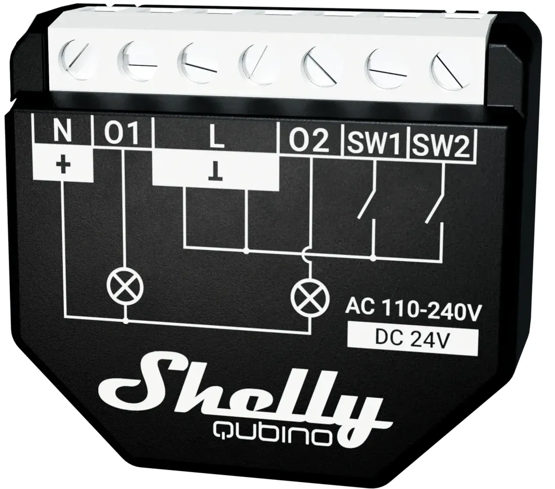
• N: Neutral terminal
• L: Live terminals (110–240 V AC)
• O1: Load circuit 1 output terminal
• O2: Load circuit 2 output terminal
• SW1: Switch/push-button input terminal (controlling O1)
• SW2: Switch/push-button input terminal (controlling O2)
• +: 24 V DC positive terminal
• : 24 V DC ground terminals
• S: S button (Fig. 5)
Wires:
• N: Neutral wire
• L: Live wire (110-240 V AC)
• +: 24 V DC positive wire
• GND: 24 V DC ground wire
DE
LEGENDE
Geräteanschlüsse:
• N: Klemme für Neutralleiter
• L: Klemmen für Phase (110-240 V AC)
• O1: Ausgangsklemme des Lastkreises 1
• O2: Ausgangsklemme des Lastkreises 2
• SW1: Schalter-/Tastereingangsklemme (Steuerung O1)
• SW2: Schalter-/Tastereingangsklemme (Steuerung O2)
• +: 24 V DC positive Anschlussklemmen
• : 24 V DC Erdungsklemmen
• S: Die S-Taste (Abb. 5)
Kabel:
• N: Neutralleiter
• L: Phasenleiter (110-240 V AC)
• +: 24 V DC Pluspolkabel
• GND: 24 V DC Massekabel
IT
LEGENDA
Terminali del Dispositiv
• N: Terminale neutro
• L: Terminali sotto tensione (110-240 V CA)
• O1: Terminale di uscita del circuito di carico 1
• O2: Terminale di uscita del circuito di carico 2
• SW1:
• SW2:
• +: Terminale positivi 24 V CC
• : T
• S: Pulsante S (Fig. 5)
Fili:
• N: Filo neutro
• L: Filo sotto tensione (110-240 V CA)
• +: Filo del positivo 24 V CC
• GND: Filo di terra 24 V CC
Fig.2/
Abb.2/
Imagen 2/
Image 2
Fig.3/
Abb.3/
Imagen 3/
Image 3
V 0.0.6 1/2
Fig.4/
Abb.4/
Imagen 4/
Image 4
Fig.5/
Abb.5/
Imagen 5/
Image 5